Wiring Cable GPS Tracker Concox GT06N
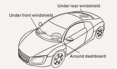
1. GPS Tracker Installation Position
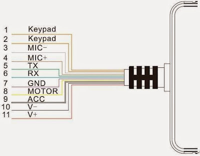
2. Wiring Diagram of The Concox GT06N GPS Tracker
| No | Specification | Color | Function |
| 1.2 | Keypad | Orange / Orange | Connection to the SOS button |
| 3.4 | MIC-,MIC+ | Black / Red | Connection to Microphone |
| 5 | TX | Green | Send data (TX) / backup |
| 6 | RX | White | Receive data (RX) / backup |
| 7 | GND | Black | Ground wire |
| 8 | MOTOR | Yellow | Connection to relay control line |
| 9 | ACC | White | Connection to ACC ignition |
| 10 | V- | Black | Connection to the vehicle battery (-) |
| 11 | V+ | Red | Connection to the vehicle battery (+) |
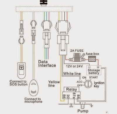
3. Wiring Diagram to Device
- The minimum normal installation is the rightmost three cables. Red (V+), black (V-), and white (ACC) colors
- Relay is used to cut off the electricity or fuel lines of the vehicle
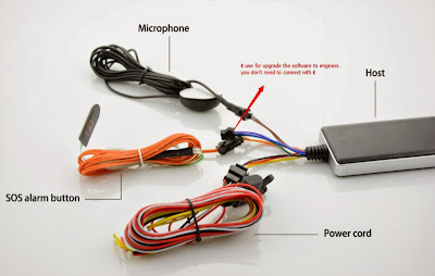
- The data cable is only used by technicians


Post a Comment